A properly calibrated irrigation system can be an efficient and uniform method for land application of liquid nutrients. Application should be done at a time and at a rate so that polluted runoff does not enter the waters of the state. Total nitrogen applied annually must not exceed the design for an approved system. Thus, depth of annual application depends upon the nutrient (nitrogen) analysis of the effluent.
Three performance characteristics are critical to proper land application of lagoon effluent by irrigation. These performance characteristics are determined by site conditions and requirements as shown in Table 1.
Table 1
| Performance characteristic | Determined by |
|---|---|
| Sprinkler application rate | Soil infiltration rate or soil permeability |
| Depth of application per irrigation event | Soil water holding capacity (depends on soil type and soil moisture content at time of irrigation) |
| Total depth of effluent applied annually | Amount of nitrogen or other limiting nutrient allowed annually under nutrient management plan |
Sprinkler application rate is a characteristic of sprinkler hardware and operating parameters (i.e., nozzle type, size, trajectory, and pressure). Hence sprinklers should be selected to be compatible with soil infiltration rate or permeability. If sprinkler application rate is higher than soil infiltration rate, the possibility for runoff is increased. Since runoff must be prevented when irrigating lagoon effluent, sprinklers are often selected for the lowest application rate possible.
Depth of application per irrigation event should be matched to the water holding capacity of the soil (Table 2). Exceeding the water holding capacity of the soil can result in runoff and contamination of surface water. Depth of application is determined by duration of operation in the case of stationary sprinklers, and by travel speed in the case of traveling sprinklers.
Table 2
Available water holding capacity of various soils
| Soil type | Moisture capacity per feet of soil depth |
|---|---|
| Coarse sands | 0.25 to 0.75 inches |
| Fine sands | 0.75 to 1.00 inches |
| Loamy sands | 1.10 to 1.20 inches |
| Sandy loams | 1.25 to 1.40 inches |
| Fine sandy loam | 1.50 to 2.00 inches |
| Silt loam | 2.00 to 2.50 inches |
| Silty clay loam | 1.80 to 2.00 inches |
| Silty clay | 1.50 to 1.70 inches |
| Clay | 1.20 to 1.50 inches |
The total depth of effluent applied annually should provide the target amount of nutrients to the receiving area on a yearly basis as specified in the nutrient management plan. This may be accomplished in a single irrigation event, or may require several separate applications, depending on site conditions.
Application rate
The maximum allowable rate of application (inches per hour) to prevent runoff depends on the intake rate of the soil. Intake rate of an initially dry soil typically decreases at a high rate as water is added and approaches the permeability of the soil. County soil surveys give the permeability of soils in inches per hour and the available water holding capacity in inches per inch. The total amount (inches) of an application depends upon the water holding capacity (moisture deficit) of the soil at the time of application. Contact your local Natural Resources Conservation Service office for a current soil survey. If soil surveys are not available, the data in Tables 2 and 3 may be used as a guide. Table 4 is a guide for determining soil moisture content by feel and appearance.
Table 3
Maximum water application rates (From MWPS18). Soils usually absorb water at a faster rate if applied in light applications (3/4-inch to 1-1/2-inch or less) when the soil is dry
| Soil characteristics | 0 percent to 5 percent slope | |
|---|---|---|
| Cover | Bare | |
| Clay; very poorly drained | 0.3 inches per hour | 0.15 inches per hour |
| Silty surface; poorly drained, clay and claypan subsoil | 0.4 inches per hour | 0.25 inches per hour |
| Medium textured surface soil; moderately to imperfectly drained profile | 0.5 inches per hour | 0.30 inches per hour |
| Silt loam, loam and very sandy loam; well to moderately well drained | 0.6 inches per hour | 0.40 inches per hour |
| Loamy sand, sandy loam, or peat; well drained | 0.9 inches per hour | 0.60 inches per hour |
| Reduce application rates on sloping ground | ||
| Slope | Application rate reduction | |
| 0 to 5 percent | 0 percent | |
| 6 to 8 percent | 20 percent | |
| 9 to 12 percent | 40 percent | |
| 13 to 20 percent | 60 percent | |
| over 20 percent | 75 percent | |
Table 4
Guide for determining soil moisture content (From MWPS18)
| Moisture condition | Percent of available moisture remaining in soil | Soil texture | ||
|---|---|---|---|---|
| Sand to sandy loam | Loam to silt loam | Clay loam to clay | ||
| Dry | 0 percent Wilting point |
Dry, loose, flows through fingers. | Powdery, sometimes slightly crusted but easily broken into powder. | Hard, baked, cracked; difficult to break into powder. |
| Low | 50 percent or less | Loose, feels dry | Forms a weak ball when squeezed but will not stick to tools. | Pliable, but not slick, balls under pressure. Sticks to tools. |
| Fair | 50 percent to 75 percent | Balls under pressure but seldom holds together when bounced in hand. | Forms a ball somewhat plastic, sticks slightly with pressure. Does not stick to tools. | Forms a ball, ribbons out between thumb and forefinger, has a slick feeling. |
| Good | 75 percent to 100 percent | Forms a weak ball, breaks easily when bounced in the hand; can feel moistness. | Forms a ball, very pliable, sticks readily, clings slightly to tools. | Easily ribbons out between thumb and forefinger, has a slick feeling, very sticky. |
| Ideal | 100 percent | Soil mass clings together. Upon squeezing, outline of ball is left on hand. | Wet outline of ball is left on hand when soil is squeezed. Sticks to tools. | Wet outline of ball is left on hand when soil is squeezed. Sticky enough to cling to fingers. |
Table 5
Discharge of big gun nozzles (From MWPS18). Taper bore nozzles have the greatest stream integrity, longest throw distance and minimum wind distortion. Ring nozzles have better stream breakup for lower pressure operation and delicate crops. Ring nozzles catch animal hair on the nozzle lip and plug more often than taper bore nozzles. Diameter is the size of the area irrigated; gpm is the application rate
| Nozzle trajectory | ||||||||||||||
|---|---|---|---|---|---|---|---|---|---|---|---|---|---|---|
| Angle | 24 degrees | 27 degrees | ||||||||||||
| Taper bore | 0.6 inch | 0.7 inch | 0.9 inch | 1.1 inches | 1.3 inches | 1.5 inches | 1.75 inches | |||||||
| Ring nozzle | n/a | 0.86 inch | 1.08 inches | 1.26 inches | 1.41 inches | 1.74 inches | 1.93 inches | |||||||
| Pressure | gpm | Diameter | gpm | Diameter | gpm | Diameter | gpm | Diameter | gpm | Diameter | gpm | Diameter | gpm | Diameter |
| 50 psi | 74 | 225 feet | 100 | 250 feet | 165 | 290 feet | 255 | 330 feet | ||||||
| 60 psi | 81 | 240 feet | 110 | 265 feet | 182 | 305 feet | 275 | 345 feet | 385 | 390 feet | 515 | 430 feet | 695 | 470 feet |
| 70 psi | 88 | 250 feet | 120 | 280 feet | 197 | 320 feet | 295 | 360 feet | 415 | 410 feet | 555 | 450 feet | 755 | 495 feet |
| 80 psi | 94 | 260 feet | 128 | 290 feet | 210 | 335 feet | 315 | 375 feet | 445 | 430 feet | 590 | 470 feet | 805 | 515 feet |
| 90 psi | 100 | 270 feet | 135 | 300 feet | 223 | 345 feet | 335 | 390 feet | 475 | 445 feet | 626 | 485 feet | 855 | 535 feet |
| 100 psi | 106 | 280 feet | 143 | 310 feet | 235 | 355 feet | 355 | 400 feet | 500 | 460 feet | 660 | 500 feet | 900 | 550 feet |
| 110 psi | 111 | 290 feet | 150 | 320 feet | 247 | 365 feet | 370 | 410 feet | 525 | 470 feet | 695 | 515 feet | 945 | 565 feet |
| 120 psi | 157 | 330 feet | 258 | 375 feet | 385 | 420 feet | 545 | 480 feet | 725 | 530 feet | 985 | 580 feet | ||
| 130 psi | 565 | 485 feet | 755 | 540 feet | 1025 | 590 feet | ||||||||
The average application rate of an irrigation sprinkler varies with nozzle opening size, number of nozzles (usually 1 to 3 per sprinkler), pressure and wetted diameter. Sprinklers with one large nozzle will reduce clogging problems when irrigating with animal wastewater. Big guns generally have only one large nozzle, specifically designed for long-throw distance. Wetted diameter varies with nozzle size, pressure and sprinkler angle. Data for sprinklers and big guns can be found in the manufacturer's literature. Table 5 has general data for big guns, if manufacturer's data are not available for planning.
Application rate varies with distance from the sprinkler (or gun). If the sprinkler produces a triangular application pattern, proper spacing should achieve a nearly uniform application depth. Sprayer application pattern can vary with operating pressure. To attain acceptable application uniformity with multiple sprinkler setups, the sprinkler spacing should be 65 percent to 80 percent of the wetted diameter. Overall uniformity can be affected by wind velocity. If possible, try to irrigate when the wind is under 5 mph. Sprinkler spacing variations with wind are given in Table 6. High trajectory sprinklers are used for low wind conditions to obtain maximum distance of throw. Low trajectory sprinklers will give shorter distance of throw and a minimum of pattern distortion.
Table 6
Typical sprinkler spacing with adjustment for wind
| Wind speed | Sprinkler spacing |
|---|---|
| 0 miles per hour | 70 percent of wetted diameter |
| 10 miles per hour | 60 percent of wetted diameter |
| over 10 miles per hour | 50 percent of wetted diameter |
Calibration of stationary big gun sprinkler systems
The average rate of application of a stationary sprinkler, operating full circle, is calculated as follows:
The average rate and depth of application from multiple settings of a stationary gun or a solid set system vary with the net area covered from a given sprinkler location. Sprinkler locations are usually in a square or rectangular pattern but may be in a triangular pattern (Figure 1).
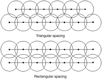 Figure 1
Effect of sprinkler spacing and arrangement. Note that the rectangular pattern requires closer spacing to achieve full coverage and reasonable uniformity.
Examples
The following equations are aids for selecting sprinkler equipment and developing management procedures for sprinkler operation.
System flow rate required to pump a lagoon in a given number of 8-hour days
Equation 1
Q = 0.0156 x V/N
Where
Q = system flow rate, gallons per minute
V = lagoon pumpdown volume, cubic feet
N = number of 8-hour days to pump lagoon
Average application rate of a single-set, or multi-set sprinkler system For a single-set sprinkler:
Equation 2
AR = 122.6 x Q/(WD)2
For a multi-set sprinkler system:
Equation 3
AR = 96.3 x Q/(WD x SP)2
Where
AR = average application rate, inches per hour
Q = system flow rate, gallons per minute
WD = wetted diameter of sprinkler, feet
SP = sprinkler spacing, fraction of wetted diameter
Time to operate system to obtain a given depth of application
Equation 4
TD = D/AR
Where
TD = time to operate sprinkler to obtain a given depth of application, hour
D = depth of application, in
AR = application rate, inches per hour
Time to operate system to obtain a given amount of nutrient per acre
Equation 5
TN = 0.0368 x NA/(AR x C)
Where
TN = time to operate sprinkler to obtain a given amount of nutrient per acre
NA = target nutrient application, pounds per acre
AR = application rate, inches per hour
C = nutrient content in lagoon effluent, pounds per 1,000 gallons
Example 1
A 200-cow dairy has an annual pumpdown volume of 400,000 cubic feet. It is desired to accomplish this pumpdown in 12 days of eight hours pumping time each. Select a single-set, stationary gun sprinkler to apply the effluent to a soil-plant filter with a medium textured silty clay soil that is moderately drained. The receiving area will have a vegetative cover, and slopes are in the range of 6 percent to 8 percent. Laboratory tests show a nitrogen concentration of 2.8 pounds per 1,000 gallons in the lagoon effluent. Target annual nitrogen application is 140 pounds per acre. Use the above equations and data in Tables 2, 3, 4 and 5; select the sprinkler and calculate the appropriate operating time for each sprinkler setting, and the total operating time to achieve the target nitrogen application rate.
- Calculate the system flow rate needed to pump the lagoon in 12 days using Equation 1.
Q = 0.0156 x 400,000 ÷ 12 = 520 gallons per minute
- Select a sprinkler that will give this flow rate from Table 5.
Two of the 27-degree trajectory nozzles listed would give the desired flow rate. A 1.41-inch ring nozzle operating at 110 psi gives 525 gpm with a wetted diameter of 470 feet. A 1.74-inch ring nozzle operating at 60 psi gives 515 gpm with a wetted diameter of 430 feet.
- Check sprinkler application rate for compatibility with soil infiltration rate. From Table 4, a moderately drained, medium textured silty clay soil has a maximum application rate of 0.5 inches per hour with a vegetative cover. This rate should be reduced by 20 percent since slopes are 6 percent to 8 percent. Target application rate is then:
0.5 inches per hour x 0.8 = 0.4 inches per hour
Calculate application rate for the nozzles noted previously using Equation 2 for single-set operation.
1.41-inch ring nozzle
AR = 122.6 x 525 ÷ (470)2 = 0.29 inches per hour
1.74-inch ring nozzle
AR = 122.6 x 515 ÷ (430)2 = 0.34 inches per hour
Since both of these nozzles have suitable application rates, (less than 0.4 inches per hour) selection might be based on pressure requirement or some other factor. Note that a gun spacing of 70 percent of wetted diameter (multiple gun set) would increase application rate by about 60 percent. If application rate is greater than the maximum for a given soil, take care to irrigate with light applications when the soil is dry. Assume that the 1.41-inch ring nozzle will be used in this example.
- Calculate time to operate sprinkler to obtain a given depth of application. Assume that irrigation will take place when the soil is at the 50 percent moisture condition, and that the applicable root zone depth is 1.5 feet. From Table 2, a silty clay soil has a water holding capacity of 1.6 inches per foot depth of soil. The depth of water to apply is calculated as follows.
Depth = 1.6 inches [er feet x 1.5 feet x 0.5 = 1.2 inches
Calculate the time to apply 1.2 inches using Equation 4.
TD = 1.2 ÷ 0.29 = 4.1 hours
The sprinkler should be operated 4.1 hours to achieve the target application depth of 1.2 inches.
- Calculate the total time required to apply 140 pounds of nitrogen per acre annually, using Equation 5.
TN = 0.0368 x 140 ÷ (0.29 x 2.8) = 6.3 hours
Since the operating time for nitrogen is greater than the operating time for soil conditions, the total annual operating time of 6.3 hours could be broken into two equal irrigation events of 3.15 hours each. This approach would minimize the risk of runoff, and may allow irrigating on soil with a higher moisture content, since less water will be applied each time.
Calibration of traveling big gun sprinkler systems
The sprinklers on traveling big guns are usually equivalent to stationary big guns. However, the sprinkler may be operated part-circle to keep a dry travel lane ahead of the traveling gun. This increases the instantaneous application rate due to the decreased area of application, and also slightly affects the uniformity of application. (The application rate for part-circle gun operation may be found by dividing the rate in inches per hour for full-circle operation by the fraction of full-circle the gun is operated.) The depth of liquid applied by a traveling gun depends on the flow rate (gpm), the lane spacing and the travel speed. Table 7 has depth of water applied as a function of these variables. Table 8 shows acres irrigated per set as a function of lane spacing and travel distance. Table 9 recommends lane spacings for windy conditions.
Table 7
Water applied by traveling big guns (From MWPS18). Average water depth applied, inches = (1.605 x sprinkler gpm) ÷ (lane spacing, feet x travel speed, feet per minute). To convert table to gallons per acre, multiply by 27,150
| Sprinkler rate | Travel lane spacing | Travel speed, feet per minute | |||||||
|---|---|---|---|---|---|---|---|---|---|
| 0.4 | 0.5 | 1 | 2 | 4 | 6 | 8 | 10 | ||
| Water applied, inches | |||||||||
| 50 gpm | 105 feet | 1.9 | 1.5 | 0.76 | 0.38 | 0.19 | 0.13 | 0.096 | 0.076 |
| 125 feet | 1.6 | 1.3 | 0.64 | 0.32 | 0.16 | 0.11 | 0.08 | 0.064 | |
| 155 feet | 1.3 | 1.0 | 0.52 | 0.26 | 0.13 | 0.09 | 0.065 | 0.052 | |
| 60 gpm | 110 feet | 2.2 | 1.8 | 0.88 | 0.44 | 0.22 | 0.15 | 0.109 | 0.088 |
| 130 feet | 1.9 | 1.5 | 0.74 | 0.37 | 0.19 | 0.12 | 0.093 | 0.074 | |
| 160 feet | 1.5 | 1.2 | 0.60 | 0.30 | 0.15 | 0.10 | 0.075 | 0.060 | |
| 70 gpm | 115 feet | 2.4 | 2.0 | 0.98 | 0.49 | 0.24 | 0.16 | 0.122 | 0.098 |
| 140 feet | 2.0 | 1.6 | 0.80 | 0.40 | 0.20 | 0.13 | 0.100 | 0.080 | |
| 170 feet | 1.7 | 1.3 | 0.66 | 0.33 | 0.17 | 0.11 | 0.083 | 0.066 | |
| 80 gpm | 120 feet | 2.7 | 2.1 | 1.07 | 0.54 | 0.27 | 0.18 | 0.134 | 0.107 |
| 145 feet | 2.2 | 1.8 | 0.89 | 0.44 | 0.22 | 0.15 | 0.111 | 0.089 | |
| 180 feet | 1.8 | 1.4 | 0.71 | 0.36 | 0.18 | 0.12 | 0.089 | 0.071 | |
| 90 gpm | 125 feet | 2.9 | 2.3 | 1.16 | 0.58 | 0.29 | 0.19 | 0.144 | 0.116 |
| 150 feet | 2.4 | 1.9 | 0.96 | 0.48 | 0.24 | 0.16 | 0.120 | 0.096 | |
| 185 feet | 2.0 | 1.6 | 0.78 | 0.39 | 0.20 | 0.13 | 0.098 | 0.078 | |
| 100 gpm | 165 feet | 2.4 | 1.9 | 0.97 | 0.49 | 0.24 | 0.16 | 0.12 | 0.10 |
| 200 feet | 2.0 | 1.6 | 0.80 | 0.40 | 0.20 | 0.13 | 0.10 | 0.08 | |
| 200 gpm | 165 feet | 4.9 | 3.9 | 1.9 | 1.0 | 0.5 | 0.32 | 0.24 | 0.20 |
| 200 feet | 4.0 | 3.2 | 1.6 | 0.8 | 0.4 | 0.27 | 0.20 | 0.16 | |
| 300 gpm | 200 feet | 6.0 | 4.8 | 2.4 | 1.2 | 0.6 | 0.40 | 0.30 | 0.24 |
| 270 feet | 4.5 | 3.6 | 1.8 | 0.9 | 0.4 | 0.30 | 0.22 | 0.18 | |
| 400 gpm | 240 feet | 6.7 | 5.4 | 2.7 | 1.3 | 0.7 | 0.45 | 0.33 | 0.27 |
| 300 feet | 5.4 | 4.3 | 2.1 | 1.1 | 0.5 | 0.36 | 0.27 | 0.21 | |
| 500 gpm | 270 feet | 7.4 | 5.9 | 3.0 | 1.5 | 0.7 | 0.50 | 0.37 | 0.30 |
| 330 feet | 6.1 | 4.9 | 2.4 | 1.2 | 0.6 | 0.41 | 0.30 | 0.24 | |
| 600 gpm | 270 feet | 8.9 | 7.1 | 3.6 | 1.8 | 0.9 | 0.59 | 0.45 | 0.36 |
| 330 feet | 7.3 | 5.8 | 2.9 | 1.5 | 0.7 | 0.49 | 0.37 | 0.29 | |
| 700 gpm | 270 feet | 10.4 | 8.3 | 4.2 | 2.1 | 1.0 | 0.69 | 0.52 | 0.42 |
| 330 feet | 8.5 | 6.8 | 3.4 | 1.7 | 0.9 | 0.57 | 0.43 | 0.34 | |
| 800 gpm | 300 feet | 10.7 | 8.6 | 4.3 | 2.1 | 1.1 | 0.71 | 0.54 | 0.43 |
| 360 feet | 8.9 | 7.1 | 3.6 | 1.8 | 0.9 | 0.59 | 0.45 | 0.36 | |
| 900 gpm | 300 feet | 12.0 | 9.6 | 4.8 | 2.4 | 1.2 | 0.80 | 0.60 | 0.50 |
| 360 feet | 10.0 | 8.0 | 4.0 | 2.0 | 1.0 | 0.67 | 0.50 | 0.40 | |
| 1,000 gpm | 330 feet | 12.2 | 9.7 | 4.9 | 2.4 | 1.2 | 0.81 | 0.61 | 0.50 |
| 400 feet | 10.0 | 8.0 | 4.0 | 2.0 | 1.0 | 0.67 | 0.50 | 0.40 | |
Table 8
Acres irrigated per setting by traveling big guns (from MWPS18). For best watering uniformity, make lane spacing 50 percent to 70 percent of the sprinkler wetted diameter
| Lane spacing | 600 feet ravel distance | 1,000 feet travel distance |
|---|---|---|
| 100 feet | 1.5 acres per set | 2.3 acres per set |
| 120 feet | 1.8 acres per set | 2.8 acres per set |
| 140 feet | 2.1 acres per set | 3.2 acres per set |
| 160 feet | 2.4 acres per set | 3.7 acres per set |
| 180 feet | 2.7 acres per set | 4.1 acres per set |
| 200 feet | 3.0 acres per set | 4.6 acres per set |
| 220 feet | 3.3 acres per set | 5.1 acres per set |
| 240 feet | 3.6 acres per set | 5.5 acres per set |
| 260 feet | 3.9 acres per set | 6.0 acres per set |
| 280 feet | 4.2 acres per set | 6.4 acres per set |
| 300 feet | 4.5 acres per set | 6.9 acres per set |
| 320 feet | 4.8 acres per set | 7.3 acres per set |
| 340 feet | 5.2 acres per set | 7.8 acres per set |
| 360 feet | 5.5 acres per set | 8.3 acres per set |
| 380 feet | 5.8 acres per set | 8.7 acres per set |
| 400 feet | 6.1 acres per set | 9.2 acres per set |
Table 9
Maximum lane spacing for traveling big guns (From MWPS18)
| Sprinkler wetted diameter of sprinkler | Percent of wetted diameter | ||||||
|---|---|---|---|---|---|---|---|
| 50 | 55 | 60 | 65 | 70 | 75 | 80 | |
| Wind over 10 miles per hour | Wind up to 10 miles per hour | Wind up to 5 miles per hour | No wind | ||||
| 200 feet | 100 | 110 | 120 | 130 | 140 | 150 | 160 |
| 250 feet | 125 | 137 | 150 | 162 | 175 | 187 | 200 |
| 300 feet | 150 | 165 | 180 | 195 | 210 | 225 | 240 |
| 350 feet | 175 | 192 | 210 | 227 | 245 | 262 | 280 |
| 400 feet | 200 | 220 | 240 | 260 | 280 | 300 | 320 |
| 450 feet | 225 | 248 | 270 | 292 | 315 | 338 | 360 |
| 500 feet | 250 | 275 | 300 | 325 | 350 | 375 | 400 |
| 550 feet | 275 | 302 | 330 | 358 | 385 | 412 | 440 |
| 600 feet | 300 | 330 | 360 | 390 | 420 | ||
The following equations are aids in calibrating and managing the operation of traveling gun sprinklers.
Average application rate of a traveling gun sprinkler:
Equation 6
AR = 122.6 x Q ÷ (WD x WD x F)
Where
AR = average application rate, inches per hour
Q = flow rate, gallons per minute
WD = wetted diameter of sprinkler, feet
F = fraction of full circle operation
Speed to operate a traveling gun sprinkler to obtain a given application depth, inches
Equation 7
S = 1.605 x Q ÷ (SP x D)
Where
S = travel speed, feet per minute
Q = flow rate, gallons per minute
SP = traveling gun lane spacing, feet
D = depth of water applied
Depth of water to apply to obtain a given nutrient application rate
Equation 8
D = 0.0368 x NA ÷ C
Where
D = depth of water to apply, inches
NA = target nutrient application, pounds per acre
C = nutrient content in lagoon effluent, pounds per 1,000 gallons
Example 2
A traveling gun is to be used to apply lagoon effluent under the conditions noted in Example 1. Assume that the nozzle will be operated part-circle with a 45-degree open segment to maintain a dry travel lane. Assume the traveling gun will use the same nozzle selected in Example 1. Calculate the gun travel speed required to apply the proper depth with the 50-percent soil-moisture condition. Also calculate the total depth-to-apply annually to obtain 140 pounds of nitrogen per acre.
- Check sprinkler application rate for compatibility with soil infiltration rate. The fraction of full circle operation is
(360 - 45) ÷ 360 = 0.875
Using the 1.41-inch ring nozzle, and Equation 6.
AR = 122.6 x 525 ÷ (470 x 470 x 0.875) = 0.33 inches per hour
Since this is less than the 0.4 inch per hour soil infiltration rate, the application rate is acceptable without modification.
- Calculate the travel speed required to apply the proper depth (1.2 inches) under 50 percent soil-moisture conditions. Use Equation 7 and assume a lane spacing of 70 percent of wetted diameter.
S = 1.605 x 525 ÷ (470 x 0.7 x 1.2) = 2.13 feet per minute
- Calculate the depth of water to apply to obtain 140 pounds of nitrogen per acre, using Equation 8.
D = 0.0368 x 140 ÷ 2.8 = 1.84 inches
Since this depth is greater than the 1.2 inches for the 50 percent soil-moisture condition, the target nitrogen application will have to be obtained using two passes, or with a single pass under drier soil conditions. If two passes were used, each applying 1.84 ÷ 2 = 0.92 inches, gun travel speed would be calculated as follows using Equation 7.
S = 1.605 x 525 ÷ (470 x 0.7 x 0.92) = 2.78 feet per minute
Evaluation of application amount and uniformity
The calibration procedures above are predicated on the assumed performance of sprinklers operated at certain pressures and sprinkler spacings. To verify that the assumed performance is achieved, catch-cans for stationary sprinklers can be spaced as shown in Figures 2 and 3. Run tests until the average depth of wastewater in the cans is at least 1 inch; longer tests will reduce errors in measuring small amounts. Catch-cans for traveling guns can be placed in a line perpendicular to the direction of travel and between two adjacent travel lanes. Catch-cans should not be more than 10 feet apart. (Source: Reference number 3.)
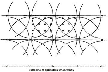 Figure 2
Catch-container for solid set (block) sprinkler layout.
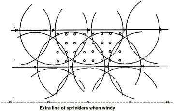 Figure 3
Catch-container layout for solid set (triangular) sprinkler layout.
For further information
- American Society of Agricultural Engineers. 1980. Design and Operation of Farm Irrigation Systems. ASAE Monograph number 3. 2950 Niles Road, St. Joseph, Mich.
- University of Arkansas Extension Publication FSA 1022-S459. 1993. Calibrating Traveling Big Gun Sprinklers for Manure Applications. University of Arkansas Cooperative Extension Service, Little Rock, Ark.
- University of Arkansas Extension Publication FSA 1023-S460. 1993. Calibrating Stationary Big Gun Sprinklers for Manure Applications. University of Arkansas Cooperative Extension Service, Little Rock, Ark.
- U.S. Department of Agriculture, Natural Resources Conservation Service. Agricultural Waste Management Field Handbook.